
Call Now: 800-298-4100 24/7 Service Available
Monday-Friday: 7:00 AM To 4:30 PM EST.
SERVICE QUESTION?
PAYMENT METHODS

- Pump Repair & Rebuild
- Electric Motor Repair
- Product and Parts Sales
- Engineered Assitance
- Laser Shaft Alignment
- Confined Space Entry
- Planned Maintenance
Impeller balancing is vital to the proper operation and maintenance of a pump. Pump Express proudly serves the balancing analysis needs for the pumping industry. We employ state of the art equipment to provide you with top notch service and repair.
You can count on our team to offer the latest technologies in pump system maintenance, pump repair and new installations. We will ensure your systems are running at peak performance saving you both repair and energy costs. For Service or to Request a Quote call a Pump Express Service representitive Today ! Toll Free : 800-298-4100.
Over the years we have earned the trust of our customers as a reliable, professional company, saving them time and money while improving their products with our expertise, experience, and wide range of technical services, including:
- Precision Pump Shaft Laser Alignment
- Dynamic Impeller Trim & Balance
- Confined Space Entry
- Pump Repair
- Pump System Installation
WHAT IS BALANCING?
Balancing is the procedure by which the mass distribution of a rotor is checked and, if necessary, adjusted in order to ensure that the vibration of the journals and/or forces on the bearings at a frequency corresponding to service speed are within specified limits.
In practical terms, balancing corrects unbalance. There are two types of unbalance, single and two plane. Single plane unbalance can be pictured by imagining a disc shaped part, such as a bicycle wheel, with a weight taped to the rim. When the bike is lifted off the ground, the wheel rotates and comes to rest with the weight at the bottom. If you were to spin the wheel, the bike would shake as the wheel tried to rotate about the center of the wheel's mass, which is no longer located at its axle. The center of mass is displaced from the geometric centerline. Another way to illustrate this effect is to place a lump of modeling clay inside a Frisbees rim and throw it. Instead of flying normally, the disc will wobble as it spins around the shifted center of mass.
Unbalance of this type is sometimes called force or static unbalance. It can be corrected by removing the weight or by adding an equal weight directly opposite (180 degrees from the unbalancing weight. Either measure would move the center of mass back to the centerline of the part.
Two-plane unbalance can be pictured by imagining a cylindrical or drum-shaped part, such as an automobile wheel's rim, with one weight attached at one end of the cylinder and another attached at the other end, but offset 180 degrees from the first weight. Note that the ends of the cylinder are in different planes. If the rim were raised off the ground, it would not rotate as the bicycle wheel did. Spinning the automobile wheel, however, would cause it to wobble as it sought to rotate about the axis of this mass, which is no longer parallel to the geometric axis. Two-plane unbalance is sometimes called couple unbalance. It can be corrected only by adding two correction weights at an axial distance from each other (see figure 1).
When both single and two-plane unbalance are present in a rotor the condition is called dynamic unbalance. To correct this type of unbalance, one must compensate for both eccentricity (caused by static unbalance) and wobble (caused by couple unbalance). In practice, any dynamic unbalance can be corrected by making adjustments in two axially separated planes. However, as the planes get close together, couple correction weights become very large.
HOW DO I BALANCE?
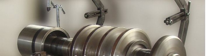
As mentioned above, parts that have significant "thickness (as opposed to disc shaped parts,) need to be balanced dynamically. For parts such as pump impellers and blowers, a horizontal overhung balancer can make the balancing process simple and easy. The part is mounted on a horizontal shaft held by a motor-driven spindle. The spindle incorporates a pair of vibration transducers that make it possible to measure dynamic unbalance.
The operator mounts tooling that will accept the part to be balanced and enters the part's dimensions (essentially the axial location of the two planes where corrections will be made and the radius at which weight will be added or removed). When the part is spun, the balancer indicates the amount of correction to be made in each plane in terms of weight to be added or removed and the angular location of the correction.
The process is computerized, and all measurements and calculations are displayed on a large color CRT. The part is rotated manually until the computer angular position display matches the present angle with the angle of unbalance correction for one of the two planes. The operator then knows precisely where to make the correction for that plane

PRICE MATCH GUARANTEE
Pump Products is dedicated to always offering the best value to our customers. We will match the price, at the time of purchase, on a Price Match Guarantee product if you find the same item at a lower price at a Designated Major Online Retailer or at a local retail competitor's store.
Here's how:
- If you find a qualifying lower price online, call 800-429-0800 and direct a customer service agent to the website with the lower price, or when visiting a Pump Products store, one of our employees will assist you.
- On qualifying products, Pump Products will then verify the current price to complete the price match.
PRICE MATCH CONDITIONS
- The manufacturer and model number must be identical.
- Pump Products will match prices of direct competitors. Our direct competitors include any retailer who sells products in both retail stores and online under the same name. Pump Products will also gladly match price on any items sold by Amazon.com (but not by a third party on Amazon.com). For further clarification, market place sellers on websites not their own are not considered direct competitors.
- Membership clubs are not considered direct competitors.
- When matching a competitor, Pump Products will follow any limitations and exclusions set by the competitor.
- The item must be first quality. Pump Products does not match prices on seconds or refurbished items.
- Pump Products does not match prices on clearance items, closeouts, liquidation sales or pricing errors.
- Competitor product must be available and in-stock at time of price match request. Price match does not apply to items promoted as “limited time,” “limited quantity,” “while supplies last” or any similar language.
- Pump Products reserves the right to limit quantities on a price match to one per customer.
- A customer can choose between the Pump Products price with a coupon/offer OR the competitor price but may not use a coupon/offer with the competitor price unless the competitor would accept it.
-
A manufacturer’s coupon may be used in combination with a price match.
Note: Any coupon that is issued from a retailer or brand that also has retail stores is considered a competitor coupon, not a manufacturer coupon. - Price Match guarantee is valid on price of item only, not on shipping and/or handling charges.